|
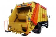
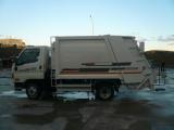
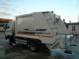
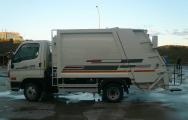
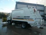
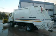
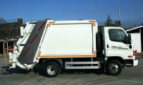
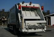
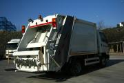
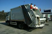
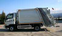
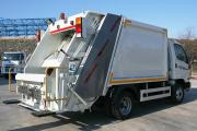
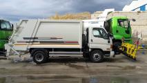
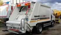
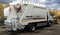
13+1,5 m3 HYDRAULIC REFUSE COMPACTOR TECHNICAL SPECIFICATIONS
|
|
|
|
1.BODY
|
|
1.1 - Floor is made of minimum 4 mm. thickness ST52 steel sheet.
|
|
1.2- Side walls are made of minimum 4 mm. thickness ST52 steel sheet. The shape of the side walls are
outward slightly convex.
|
|
1.3- The top of the body is made of minimum 4 mm. thickness ST52 steel sheet. The top and floor of the body
will be strength with sufficient profiles.
|
|
1.4- Front frame is made of minimum 4 mm. thickness ST52 steel sheet, rear frame is made of minimum
5 mm. thickness ST52 steel sheet
|
|
1.5- The volume capacity of the body is 13 m3. Body will be installed on the equipment chassis without
giving damage to the torsion of the chassis.
|
|
1.6- In order to move the compaction-unloading curtain by lengthways, U cross-sections are mounted on
the side of the floor.
|
|
1.7- In order to put the body on the chassis, the lifting-lugs are mounted on the top of the body.
|
|
1.8- The side walls are welded consecutively on the front rear frame.
|
|
1.9- The sides of body are flat.
|
|
2. TAILGATE
|
|
2.1- The tailgate is opened by the hydraulic cylinders which are installed on the rear-top of the body
by using hinges.
|
|
2.2- A rubber gasket, easily replaceable and custom profile will not be affected by acid, is mounted in order
to stop the body leaking.
|
|
2.3- The loading hopper volume is 1,5 m3, the garbage will be transferred by hydraulic cylinders that have
min. operating pressure 160 bars with a compacting mechanism.
|
|
2.4- The channels in the rear cover side walls compacting mechanism consists of linear moving sliders and
at the end a scoop that moves revolving and sweep the garbage in its hoop.
|
|
2.5- The sliders move on the hard rubber wedges that can be installed easily.
|
|
2.6- There is a safety cushion can be used during the maintenance between the rear cover and body.
|
|
2.7- There is a safety valve in order to stop the rear cover to fall in case of emergency when it is open.
|
|
2.8- There is a hydraulic speed control valve that can adjust the closing speed of the rear cover.
|
|
2.9- There is a garbage water draining walve or plug under the loading tank.
|
|
3. COMPACTION- UNLOADING CURTAIN
|
|
3.1- Curtain is wear-resistant, acid and can be installed easily, will be connected with polyamide skid shoes.
|
|
3.2- The curtain is moved by a double-acting telescopic cylinder and in the rear side while the body is empty.
While loading the garbage the curtain moves in front of the body by telescopic cylinder with 80 bar.
|
|
3.3- The compaction-unloading curtain moves in the U pofiles installed in the body.
|
|
3.4- A rubber gasket is installed at the bottom of the curtain to sweep the garbage during unloading
of the garbage.
|
|
3.5- Depending on the intensity of garbage, the compaction ratio can be adjusted.
|
|
4.- HYDRAULIC EQUIPMENT
|
|
41.- The hydraulic power will be transmitted to the hydraulic pump by PTO installed on the ger box
of the vehicle.
|
|
4.2- First class PTO and pump will be used, PTO will be controlled from the cabin.
|
|
4.3- The oil tank is min. 90 liters and there is a conversion filter with min. 25 microns and a suction filter
with min. 125 microns on it.
|
|
4.4- There is vented tank lid, level gauge, valve and drain plug.
|
|
4.5- All hydraulic cylinder pipes are made of seamless steel pipe, the cylinder shaft is chrome coated.
|
|
4.6- The opening-closing of the rear cover and the back and forward moving of the compaction-unloading
curtain is controlled by the manual control of the direction control valve. (the system pressure is min. 160 bars)
The sliding buckets movements will be controlled by electrical direction control valve therefore all the
energy taken from the vehicle can be used for the compaction. The control valves are durable against the
250 bars pressure and has a standard safety valve.
|
|
4.7- All pipes, seamless cold-shooting adhere to DIN 2319 C standard. The whole of the hydraulic pressure
pipes are complying the SAE 100 R2 and the suction pipes comply the SAE 100 R4 standard.
|
|
5. GARBAGE CONTAINER UNLOADING SYSTEM
|
|
a) Hydraulic commanding Garbage loading mechanism can be mounted on the body.
(upon request of the customer.)
|
|
b) The disinfection mechanism will be mounted on the vehice after unloading the garbage.
|
|
6. STANDARD ACCESSORIES
|
|
a- Projector for night working.
|
|
b- Audible warning for the driver
|
|
c- Handhold and footstep for the workers.
|
|
d.- Rear cover safety
|
|
e- Mudguard and dust rubber.
|
|
f- Garbage container lifting system.
|
|
g- Rotating yellow beacon.
|
|
h- Garbage water tank
|
|
ı- Garbage water discharge gate.
|
|
k- Reflector
|
|
7. CONTROL EQUIPMENT AND OPERATION SYSTEM
|
|
7.1- The loading is controlled by the butoon installed on the right or left side of the rear cover.
|
|
7.2- On the control pannel, the control buttons and the printed circuit board are in a protected box.
|
|
7.3- On the control pannel, there is an automatic throttle system.
|
|
74.- On the control pannel, there is a throttle system, audible warning for the driver and emergency switch.
|
|
7.5- The compaction is controlled with three control handle.
|
|
8. PAINTING
|
|
8.1- Superstructure is washed with special chemical and then it is cleaned with the complete method
of sanding after purifying from the other materials and oil. After it is scattered with the paste two coat
epoxy primer and two coat acrylic elastic painting application is done. All the painting operations
are done in the oven paint cabinet.
|
|
8.2- The logo or any sign of the customer can be put on the body.
|


